 EA4FSI
4NEC2 simulation files

1. Monopole over perfect ground.
The antenna under analysis is an ideal quarter-wave monopole designed to work in the 20-metre band, adjusted to a centre frequency of 14.1 MHz. The first analysis considers an ideal monopole over a perfectly conducting ground plane. The effects of ground with finite conductivity are then examined, followed by the addition of radials to improve the ground system.
1.1. Antenna design.
In 4NEC2, the monopole is positioned along the Z-axis, perpendicular to the XY-plane (Fig. 1).
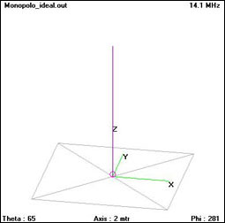
This first analysis assumes a perfectly conducting ground plane and no radials. The monopole length, optimised with 4NEC2 to minimise SWR, is 5.16 metres.
1.2. Simulation results.
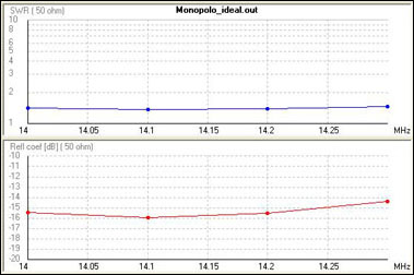
The simulated SWR is approximately 1.38 across the 20-metre band, as shown in Fig. 2.
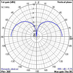
The antenna has an omnidirectional azimuthal radiation pattern over the simulated perfectly conducting ground plane. Its gain is 5.15 dBi (3 dBd), approximately 3 dB more than that of a half-wave dipole in free space (Fig. 3).
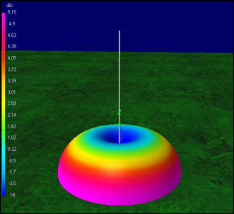
In the vertical plane, the radiation pattern has its maximum gain just at a null takeoff angle, making the antenna optimal for DX work under these ideal conditions. The radiation efficiency, as calculated by 4NEC2, is 99.96%, very close to the theoretical 100%.
2. Monopole over real ground.
Using the same design (Fig. 1), the perfectly conducting ground plane is replaced with ground having assumed average soil characteristics (conductivity 0.005 S/m and relative permittivity 13). This provides a model closer to a practical installation.
2.1 Simulation results.
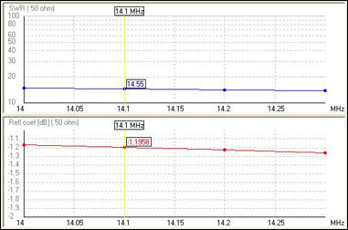
With the same monopole length of 5.16 metres, the simulated SWR rises to 14.5. The feed-point impedance is substantially different from 50 Ω, so an impedance transformer or antenna tuner is required.
Although the antenna is still omnidirectional, the first observed effect of imperfect ground is a rise in the main radiation lobe (Fig. 6).
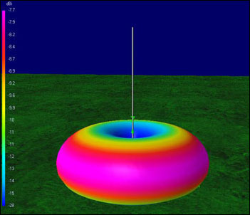
A vehicle-roof installation provides a useful comparison, although its finite conducting surface is different from the lossy-ground model simulated here. A monopole mounted near the edge of a vehicle roof may show less distortion towards the conducting roof than away from it, where the available conducting surface is smaller (Fig. 7).
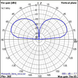
The simulated antenna gain is −7.74 dBi at a take-off angle of 25° above the ground. The antenna therefore has negative gain. Its radiation efficiency is only 5.22%, because return currents flow through soil with relatively poor electrical conductivity. The results would be worse over drier soil.
3. Monopole with one radial or counterpoise.
The previous analysis suggests that improving the ground return path can reduce distortion of the radiation pattern and improve radiation efficiency. This can be achieved using radials or a counterpoise. The distinction between the terms radial and counterpoise is discussed in detail by L. B. Cebik (W4RNL).
The following analysis takes into account only one radial or counterpoise, which is the option chosen by several manufacturers of portable vertical HF antennas. Furthermore, we will consider that both the monopole and the counterpoise are very close to the ground.
There are several approaches to choosing radial length, depending on installation height, the number of radials and ground conditions. For the installation context discussed in the ARRL Antenna Book, a minimum length of half the operating wavelength is recommended. Here, 4NEC2 is used to optimise the counterpoise length for the configuration studied.
In the 4NEC2 simulation, the entire structure is raised 0.1 m above the ground to avoid direct contact between the counterpoise and the soil.
3.1. Antenna design.
In 4NEC2, the monopole is positioned along the Z-axis, perpendicular to the XY-plane (Fig. 8).
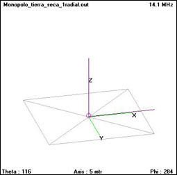
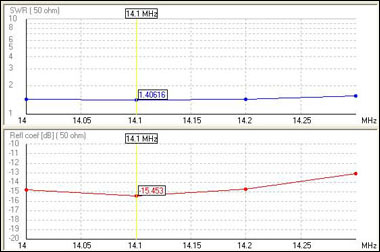
In the simulation, the radial or counterpoise extends along the X-axis of the ground plane. The monopole length is set to the initial value of 5.16 metres, and 4NEC2 is used to optimise the counterpoise length for minimum SWR. The resulting counterpoise is 4.79 metres long, with an SWR of 1.41. This result applies to the particular monopole, operating frequency and ground conditions simulated.
3.2. Simulation results.
After optimising the counterpoise length, the SWR is around 1.4 and remains nearly constant across the 20-metre band (Fig. 9).
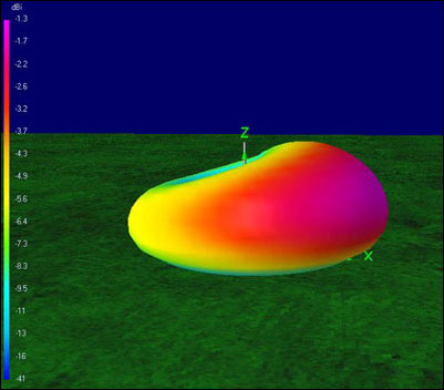
In the simulated configuration, the radiation pattern is no longer omnidirectional: the antenna has greater gain towards the counterpoise (the +X direction in this example).
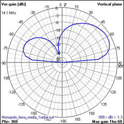
In the vertical-plane radiation pattern (Fig. 11), the main lobe points broadly towards the counterpoise, with a maximum gain of −1.3 dBi at a take-off angle of 30°. The front-to-back ratio is 4.6 dB, so for this configuration the counterpoise can be oriented towards the distant station. The radiation efficiency is 16%.
Compared with example 2, adding the counterpoise increases the simulated antenna gain by approximately 6.5 dB and roughly triples the radiation efficiency. A counterpoise of suitable length can also improve impedance matching across the operating band.
For the simulated configuration, a single radial or counterpoise of suitable length improves radiation efficiency and gain in the direction of the counterpoise.
The counterpoise forms part of the antenna system, so its length must be considered when optimising SWR.
4. Monopole with 4 radials.
In the previous example, a single radial or counterpoise improved the simulated gain and radiation efficiency, but the monopole no longer had an omnidirectional radiation pattern. Here, four symmetrically arranged radials are used to obtain an approximately omnidirectional pattern.
4.1. Antenna design.
In 4NEC2, the monopole is positioned along the Z-axis, perpendicular to the XY-plane (Fig. 12). The four radials extend along the +X, −X, +Y and −Y axes.
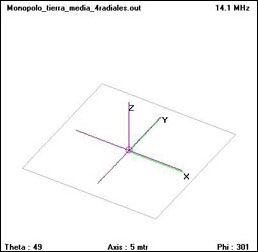
To obtain an approximately omnidirectional radiation pattern, the four radials are arranged at 90° intervals. In the 4NEC2 simulation, the structure is raised 0.1 m above the ground to avoid direct contact. The monopole is 5.16 metres long, as in the previous examples, and each radial is 4.79 metres long, as calculated in example 3.
4.2. Simulation results.
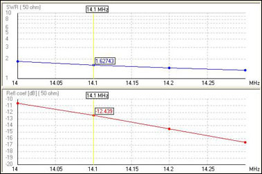
The SWR at the design frequency is 1.62, decreasing towards the upper end of the 20-metre band (Fig. 13).
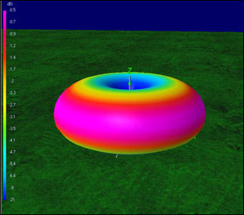
The radiation pattern is again approximately omnidirectional, thanks to the symmetrical arrangement of the four radials (Fig. 14).
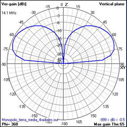
The vertical-plane radiation pattern (Fig. 15) shows a maximum gain of −0.47 dBi at a take-off angle of 25°. The radiation efficiency is 27.57%.
Compared with example 3, the simulated antenna gain improves by 0.8 dB, with the additional benefit of an approximately omnidirectional radiation pattern. Radiation efficiency is almost twice that of the single-radial configuration.
5. Conclusions.
Table 1 summarises the simulations of the ideal monopole over a perfectly conducting ground plane, the monopole over ground with assumed average soil characteristics, and the effects of adding one or four radials or counterpoises. It also includes the results for configurations with up to 256 radials.
| Antenna | Ground | Radials | Monopole length (m) | Radial length (m) | SWR (50 Ω) | Efficiency (%) | Radiation pattern | Max. gain (dBi) | F/B (dB) |
|---|---|---|---|---|---|---|---|---|---|
| Ideal monopole | Perfect | 0 | 5.16 | N/A | 1.38 | 99.96 | Omnidirectional | 5.15 | 0 |
| Monopole | Real, average | 0 | 5.16 | N/A | 14.55 | 5.22 | Omnidirectional | −7.74 | 0 |
| Monopole | Real, average | 1 | 5.16 | 4.79 | 1.41 | 15.99 | Directional | −1.29 | 4.62 |
| Monopole | Real, average | 4 | 5.16 | 4.79 | 1.63 | 27.57 | Omnidirectional | −0.47 | 0 |
| Monopole | Real, average | 8 | 5.16 | 4.79 | 1.75 | 35.2 | Omnidirectional | 0.56 | 0 |
| Monopole | Real, average | 16 | 5.16 | 4.79 | 1.75 | 39.87 | Omnidirectional | 1.12 | 0 |
| Monopole | Real, average | 32 | 5.16 | 4.79 | 1.75 | 45.81 | Omnidirectional | 1.75 | 0 |
| Monopole | Real, average | 64 | 5.16 | 4.79 | 1.75 | 50.7 | Omnidirectional | 2.19 | 0 |
| Monopole | Real, average | 128 | 5.16 | 4.79 | 1.75 | 53.1 | Omnidirectional | 2.37 | 0 |
| Monopole | Real, average | 256 | 5.16 | 4.79 | 1.75 | 53.9 | Omnidirectional | 2.43 | 0 |
The general conclusions are:
-
With the assumed average soil characteristics, the monopole’s radiation efficiency falls to approximately 5%, its gain decreases by around 12 dB, and its main radiation lobe moves to a higher elevation angle. The feed-point impedance also changes substantially. The results may be worse over drier soil, and the antenna length or matching arrangement may need to be reconsidered.
-
A single radial or counterpoise of suitable length can provide a return path for antenna currents, improve radiation efficiency and gain, and produce a relatively low SWR under the simulated conditions. The resulting radiation pattern is directional, with its maximum towards the counterpoise.
-
In the configurations studied, four symmetrically arranged radials provide an approximately omnidirectional pattern. Increasing the number of radials generally improves radiation efficiency and gain over the simulated range. The improvement between 128 and 256 radials is small: efficiency rises from 53.1% to 53.9%, and gain from 2.37 to 2.43 dBi.