 EA4FSI
| Type | Horizontal dipole |
|---|---|
| Design | REMER |
| Impedance | 50 Ω |
| Simulation | MMANA-GAL |
| Band | Single-band |
| Remarks: Length of each arm (m) = 71.25 / f (MHz) | |
 Dipole for 20 mDipolo_horiz_20m.maaDipole for 40 mDipolo_horiz_40m.maaDipole for 80 mDipolo_horiz_80m.maa
1. Antenna design and modeling
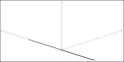
Figure 1 shows the horizontal dipole modeled in MMANA-GAL, oriented along the Y-axis.
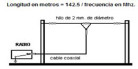
The horizontal dipole consists of two wire arms. Its approximate total length is L (m) = 142.5 / f (MHz), with each arm measuring half that length: 71.25 / f (MHz). The antenna is constructed from wire 2 mm in diameter. Table 1 shows the length of each arm for the 20 m, 40 m and 80 m bands.
| Band | Length of each arm (m) |
|---|---|
| 20 m | 5.089 |
| 40 m | 10.178 |
| 80 m | 20.357 |
2. Radiation patterns
The radiation patterns presented in this section correspond to a dipole designed for the 20-metre band. Similar patterns are obtained for the other bands. The antenna has a bidirectional radiation pattern, with lobes perpendicular to its axis. The theoretical maximum gain of a half-wave dipole in free space is approximately 2.12 dBi; actual gain and radiation patterns depend on installation height and ground conditions.
Figure 2 shows the radiation pattern of the dipole installed at a height of one-quarter of the operating wavelength.
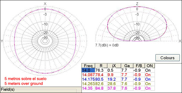
Figure 3 shows the radiation pattern of the dipole installed at a height of one-tenth of the operating wavelength.
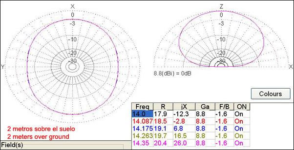
For NVIS operation, the recommended installation height is approximately one-tenth of the operating wavelength above ground. At this height, an antenna tuner may be required. For DX operation, a greater installation height is recommended.
Table 2 shows the recommended dipole installation heights for NVIS operation in each band.
| Band | Height over ground (m) |
|---|---|
| 20 m | 2.1 |
| 40 m | 4.2 |
| 80 m | 7.8 |