 EA4FSI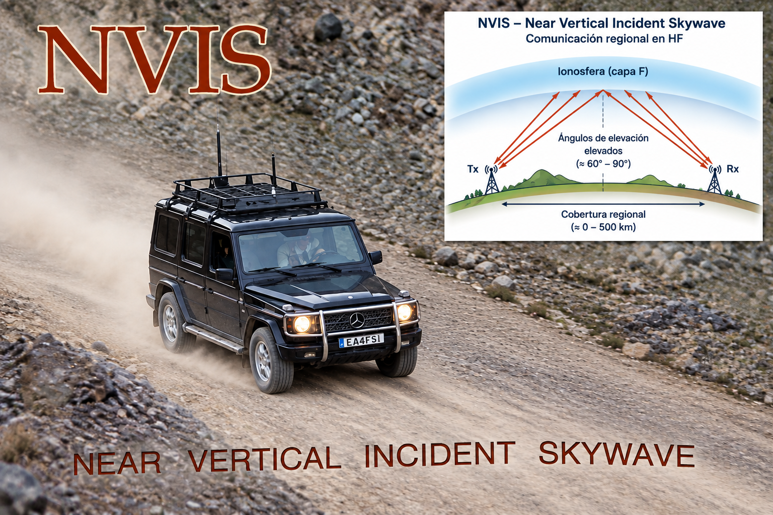
Abstract: The article describes the fundamentals of near-vertical incidence skywave (NVIS) propagation in the HF band, focusing on circuit geometry and operating frequency selection. Some NVIS antenna options for base stations and mobile operations are also presented.
Article published in the magazine of the Spanish Amateur Radio Union (URE) in November 2008.
Download original articlenvis_eb2cws.pdf · 407 kB1. Introduction
HF radio communications are commonly used to establish medium- and long-distance (DX) links through ionospheric propagation. This requires antennas whose radiation pattern has a very low take-off angle, around 3º, together with operating frequencies below the MUF (Maximum Usable Frequency) for a given distance. Low take-off angles make the first ionospheric reflection occur far from the transmitting station, increasing the communication range, but the resulting skip distance becomes a shadow zone where no radio link can be established, at least until the ground wave has completely dissipated.
For short-distance radio communications, VHF and UHF bands are normally used. Their propagation is mainly subject to reflection, multipath propagation, refraction and diffraction, with ranges from about 10 km to 60 km depending on terrain, antennas and transmitter power. Repeaters are used to extend coverage.
There is therefore a shadow zone that cannot be covered by VHF/UHF equipment because of its limited range and that is normally not covered by HF equipment either, because its radiating systems are designed for DX. A VHF/UHF repeater failure can also substantially reduce coverage.
This shadow zone can be critical in emergency communications, making it highly desirable to have systems capable of covering it. One such HF propagation mode is NVIS (Near Vertical Incidence Skywave), widely used in military environments since the Second World War but generally unfamiliar to many HF users.
Standard HF equipment can be used for NVIS. Two things must be considered: selecting a suitable operating frequency and using an antenna with NVIS characteristics.
2. Fundamentals of NVIS propagation
NVIS propagation is based on antennas with a very high take-off angle, around 70º to 90º, i.e. perpendicular or almost perpendicular to the ground plane. When transmitting in HF with such an antenna, and provided that the selected frequency is suitable, the radio wave reaches the ionosphere almost vertically and is reflected back towards Earth at a very small reflection angle, covering the shadow zone of DX HF and VHF/UHF systems.
As an example, consider an NVIS antenna whose main radiation lobe extends from 70º to 90º elevation above the ground plane.
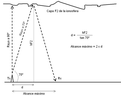 Fig. 1. Ionospheric hop geometry.
The antenna radiates throughout the region between 70º and 90º elevation. The first ionospheric reflection occurs in the F2 layer, covering the region between the transmitting station and a maximum range that can be determined using a simple trigonometric calculation.
The maximum-range ray has an elevation angle of 70º. The unknown distance “d” is half the maximum range. The second required parameter is the altitude at which reflection occurs in the F2 layer, hF2. This altitude is continuously measured by ionosondes around the world and varies mainly with the time of day.
 Fig. 2. Critical frequency and F2-layer height measurements. Click the image to enlarge.
Figure 2 shows data collected by the Ebro Observatory in Roquetes (Tarragona) on 27 September 2008. The night and day hF2 extremes were about 150 km and 310 km. At night, F1 and F2 merge into a single F layer, which also supports NVIS communications.
Using these values in the formulas shown in figure 1 gives maximum ranges between 110 km and 225 km. Depending on the time of year, hF2 can reach 400 km, giving ranges up to 300 km with the same 70º elevation angle.
If the NVIS radiation pattern is wider and extends down to about 60º elevation, the range would be even greater.
Thus, an NVIS system can establish HF communications within a radius of up to 300 km around the transmitting station, or even more, without shadow zones. These communications normally involve a single hop and require very little power; 20 W or less is often sufficient.
3. Operating frequency selection
The operating frequency is critical to correct NVIS operation. As a general rule, select a frequency approximately 10% below the critical frequency of the ionospheric F2 layer (foF2) at a given time.
foF2 should not be confused with MUF. foF2 is the maximum frequency at which a radio wave incident perpendicularly on the ionosphere can be reflected. The MUF takes non-perpendicular incidence angles into account, which in practice means that there is a different MUF for each radio-link distance.
The objective is therefore to obtain foF2 predictions or, preferably, real-time foF2 measurements from an ionosonde near the transmitting station and at a time close to the intended transmission time. foF2 varies significantly with time of day and also depends on transmitter location.
The original article points to the Center for Atmospheric Research at the University of Massachusetts Lowell station map, where foF2 and other measurements from ionosondes around the world can be found.
For Spain, the article identifies ionosondes at the Ebro Observatory (Roquetes, Tarragona) and at the Spanish National Institute of Aerospace Technology (El Arenosillo, Huelva).
Ionosonde stations provide ionograms such as the one shown in figure 3.
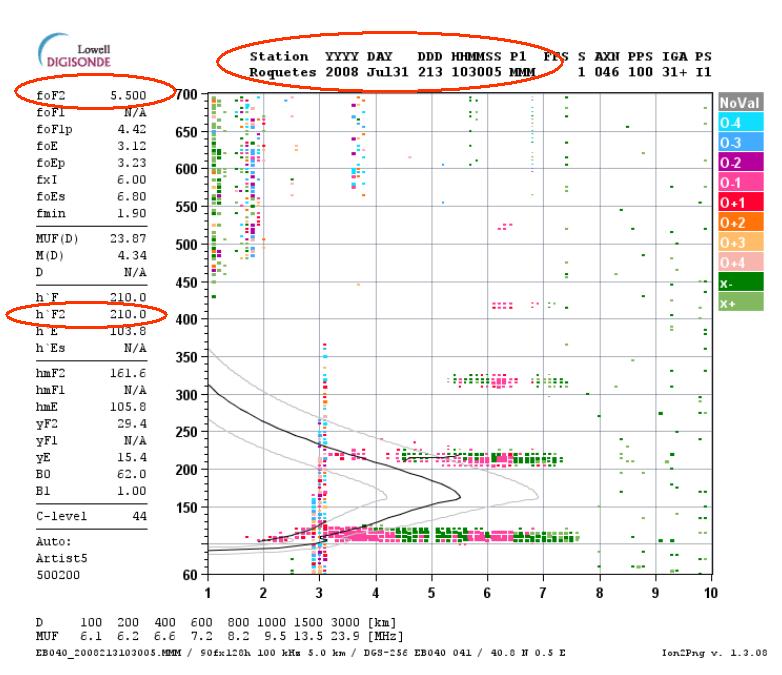 Fig. 3. Extracting the critical frequency foF2 from an ionogram. Click the image to enlarge.
The top of the ionogram shows the measurement time, in this case “2008 Jul31 213 103005”, i.e. 31 July 2008 at 10:30 UTC. The upper-left corner shows the foF2 value, which is 5.500 MHz in this case. hF2 can also be extracted for range calculations; here it is 210 km.
Applying the 10% rule, if foF2 is 5.500 MHz, the optimum NVIS operating frequency is 4.950 MHz.
If the calculated frequency cannot be used because it is not authorized, occupied, noisy or interfered with, the first authorized band immediately below the calculated frequency should be used. Transmission above foF2 should never be used, since ionospheric reflection would not occur.
4. NVIS antennas
In addition to selecting a suitable operating frequency, the other key requirement is an antenna with NVIS capability, radiating mainly between about 70º and 90º elevation above the ground plane.
One option is to purchase an antenna specifically developed for NVIS, although most manufacturers target these products towards military applications. Another option is to adapt antennas normally used for HF DX.
4.1. Base-station antennas
There are many antenna designs for NVIS. We will focus on the simplest NVIS antenna for a base station or field deployment: the horizontal wire dipole (figure 4), the same type used for DX communications. The key is its height above ground.
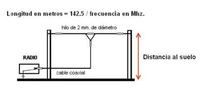 Fig. 4. Horizontal wire dipole.
The elevation pattern of a horizontal wire dipole changes substantially with its height above ground, which can readily be examined using simulation programs such as NTIA/ITS HFAnt.
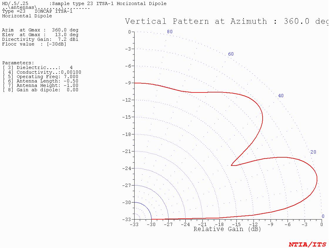 Fig. 5. Horizontal dipole one wavelength above ground. Click the image to enlarge.
At one wavelength above ground (43 m for a 7 MHz dipole), the elevation pattern has two main lobes with low take-off angles.
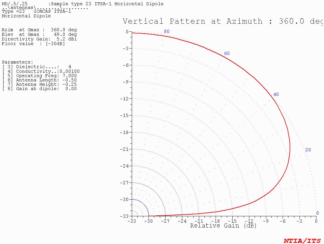 Fig. 6. Horizontal dipole one quarter wavelength above ground. Click the image to enlarge.
At one quarter wavelength above ground (10 m for a 7 MHz dipole), the elevation pattern has a single lobe with a maximum at 49º. Radiation perpendicular to the ground is also good, so this configuration can already be used for NVIS.
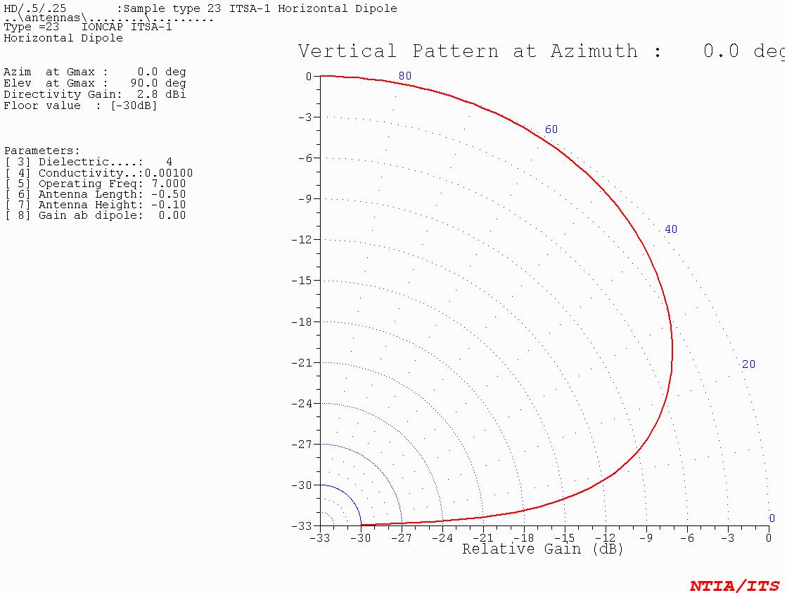 Fig. 7. Horizontal dipole one tenth wavelength above ground. Click the image to enlarge.
As the dipole is lowered further, its radiation pattern rises until, at exactly one-tenth of a wavelength above ground (4 m for a 7 MHz dipole), maximum radiation occurs at 90º, perpendicular to the ground.
Considering the 3 dB beamwidth, the dipole radiates mainly between 30º and 90º elevation, making it suitable for NVIS.
Lowering the dipole further makes the pattern higher and narrower, reducing effectiveness in the perpendicular direction and introducing additional losses from proximity to the ground. A possible solution is a second conductor close to the ground, acting as a reflector.
Ground conductivity also affects antenna performance. Some authors suggest an optimum dipole height between 0.15 and 0.25 wavelengths.
Any NVIS antenna design should also avoid secondary low-elevation radiation lobes, because they could generate a sufficiently strong ground wave to interfere with the reflected NVIS wave near the transmitter.
4.2. Mobile communications antennas
For mobile communications, where HF equipment is installed in vehicles, there are two options.
The simplest approach is to use a standard vertical antenna and fold it down so that it is parallel to the ground. The appropriate height above ground is difficult to achieve, but an approximation may provide a radiation pattern adequate for NVIS.
The other option is a purpose-built NVIS antenna. One of the most commonly used is the half-loop antenna, which can be installed on a vehicle roof. Figure 8 shows a design produced with MMANA-GAL.
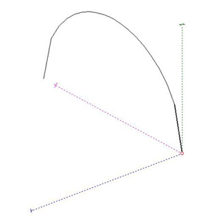 Fig. 8. NVIS half-loop antenna.
The antenna is fed from the transceiver at one end and the opposite end is connected to ground, effectively creating a predominantly magnetic loop. The loop arc is usually about 1.5 m in radius.
The main advantage over other NVIS antennas is its omnidirectional radiation pattern, as shown in figure 9, making it well suited to mobile communications.
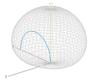 Fig. 9. Radiation pattern of an NVIS half-loop antenna.
Another advantage is its magnetic behaviour, similar to that of full-loop antennas, resulting in a high Q factor that minimizes noise and interference.
However, this type of antenna presents two main drawbacks: when installed on a vehicle roof, the radiation pattern becomes distorted, mainly towards the rear; and it can exhibit a very high capacitive impedance that is difficult to match at some frequencies. Radiation efficiency is also low and the antenna can also suffer from losses.
5. Conclusions
NVIS communications can establish HF links with ranges up to 300 km without shadow zones, filling the gap between the maximum range of VHF/UHF systems and the shadow zone of the first hop in HF DX communications. This makes them suitable for emergency operations, and they are widely used in both emergency and military environments.
Two fundamental points must be considered for NVIS operation. First, the antenna must have a sufficiently high elevation pattern, such as a horizontal dipole installed at a height of about one tenth of the operating wavelength. Second, the operating frequency must be selected below the F2-layer critical frequency (foF2), optimally around 10% below it.