

Two wire broadband HF dipole
|
Main → HF Radio Resource Center → HF Antennas → Two wire broadband HF dipole |
![]() Este artículo también está disponible en Español (this article is also available in Spanish).
Este artículo también está disponible en Español (this article is also available in Spanish).
![]() Abstract:
Abstract:
This article describes the design and simulation of a two wire broadband dipole antenna for the HF band, using the software 4Nec2. The antenna is designed to operate in the full range 3-30 MHz. Acknowledgement to EA4NA for his support in the antenna analysis.
The simulations are focused to obtain the impedance and the radiation patterns of the antenna in this band.
 |
Type: Two wire broadband dipole |
| Design: Australian | |
| Impedance: 300 ohms | |
| Simulation: 4NEC2 | Band: 3-30 MHz |
Remarks: Resistive and inductive loads. |
|

Dipolo_Banda_ancha_dos_hilos.nec
1. Design and antenna modeling.
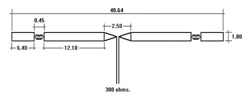
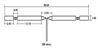
The fig.1 shows the design of the dipole. All the distances are shown in meters. From the feeding point, the structure of each leg can be described as follows:
-
Both wires must reach a separation of 1.80 meters at 1.25 meters from the feeding point. At this point, a metallic spacer is placed in order to keep the wires parallel.
-
After the first spacer, both wires spread along 12.10 meters to reach another metallic spacer.
-
At this point, there is a discontinuity of 0.45 meters with the next leg section.
-
The next leg section is made of two wires again, with one metallic spacer at the beginning and other at the end. This section has a length of 6.40 meters.
-
Both sections are joined by one carbon resistive load (330 ohms, 2 W) and one inductive load (16 uH), placed in parallel. AMSAT Argentina provides some helpful tools for the design of inductances.
All the wires are made of copper with a diameter of 1 mm. The eight spacers of the antenna are metallic with a diameter of 12.5 mm. The maximum power applied to the antenna must not exceed 350 W.
The fig.2 shows the antenna modeled with the 4Nec2 software.
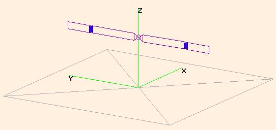
The antenna has an impedance of about 300 ohms at the feeding point, almost in all the 3-30 MHz band. It can be used with a 50 ohms coaxial line with a 4:1 balun.
2. Simulation results.
In this sections the results of the simulations with 4Nec2 are shown: calculated standing wave ratios (SWR) and radiation patterns.
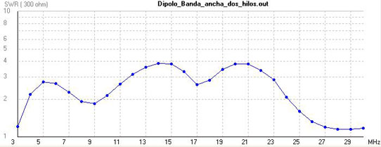
2.1 Standing wave ratios (SWR).
SWR calculations for a characteristic impedance of 300 ohms. In some cases, particularly if the antenna is placed near metallic objects, it is recommended to use an antenna tuner.
The fig.3 shows the results of the simulation for all the 3-30 MHz band, considering a characteristic impedance of 300 ohms.
2.2. Radiation patterns.
-
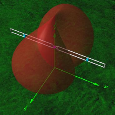
80 m band: bidirectional antenna (fig.4) with main lobes perpendicular to the antenna's axis, and losses around 0.76 dBi. The antenna also radiates in NVIS mode, presenting a loss of 0.76 dBi.
-
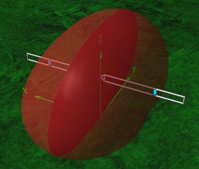
40 m band: bidirectional antenna (fig.5) with main lobes perpendicular to the antenna's axis, and gain around 0.57 dBi. The antenna also radiates in NVIS mode, presenting a loss of 0.78 dBi.
-
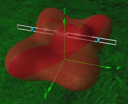
20 m band: bidirectional antenna presenting four main lobes at 30 degrees from the perpendicular to the antenna's axis (fig.6). Gain around 3.26 dBi.
-
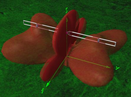
17 m band: bidirectional antenna presenting four main lobes at 55 degrees from the perpendicular to the antenna's axis (gain 8.24 dBi) and two secondary lobes perpendicular to the antenna's axis (gain 4.43 dBi). See fig.7.
|
Ismael Pellejero - EA4FSI |
 EA4FSI Home |
 HF Antennas TOC |
 HF Central |