
Marconi Antenna
|
Main → HF Radio Resource Center → HF Antennas → Marconi Antenna |
![]() Este artículo también está disponible en Español (this article is also available in Spanish).
Este artículo también está disponible en Español (this article is also available in Spanish).
![]() Abstract:
Abstract:
This article describes the characteristics of the Marconi antenna and shows the results of several simulations made with MMANA-GAL, covering models optimized for the 20 m, 40 m and 80 m bands. The goal of the simulations is to check the behaviour of the antenna both in it fundamental band of design and in the harmonic bands, taking into account the impedance and the radiation patterns.
 |
Type: Vertical wire |
| Design: REMER | |
| Impedance: 50 ohm | |
| Simulation: MMANA-GAL | Band: Multiband |
Remarks: Total length, meters = 71,25 / (F MHz) |
|
Marconi for 20 m |
Marconi for 40 m Marconi_40m.maa |
Marconi for 80 m Marconi_80m.maa |
Marconi antenna for 20m - Simulation report
Marconi_report.pdf
1. Design and antenna modeling.
The fig.1 shows the Marconi antenna modeled in MMANA-GAL, erected along the "Z" axis.
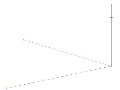
The Marconi antenna is a vertical wire with a length of 1/4 of the working wavelength, feeded through its lower end. It needs a ground plane with very good conductivity. The Marconi radiator is resonant to any odd multiple of a quarter-wave length. The length of the wire in meters is calculated as L = ( 71,25 / Frequency MHz).
2. Simulation results.
In this sections the results of the simulations with MMANA-GAL are shown, showing the calculated standing wave ratios (SWR) and radiation patterns for each band.
2.1 Standing wave ratios (SWR).
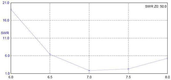
This section shows the simulated SWR at 7 MHz and 21 MHz (third harmonic) of a Marconi antenna designed for the 40 meters band.
The fig.2 shows the SWR in the band of design (7 MHz).
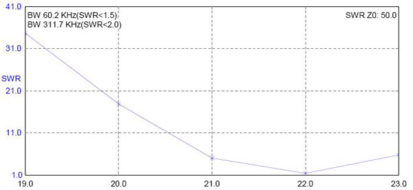
The fig.3 shows the SWR in the third harmonic band (21 MHz). We can see that, for SWR < 2, the antenna has a bandwidth of about 310 kHz in the third harmonic.
2.2. Radiation patterns.
This section shows the simulated radiation patterns at 7 MHz and 21 MHz (third harmonic) of a Marconi antenna designed for the 40 meters band..
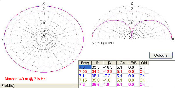
The fig.4 shows the radiation pattern in the band of design (7 MHz).
The fig.5 shows the radiation pattern in the third harmonic band (21 MHz).
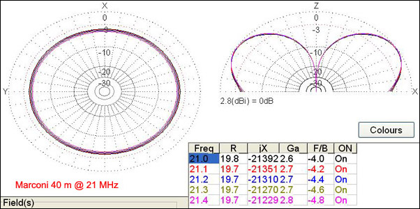
Being a vertical antenna, it isn't suitable for NVIS operation. The pattern is omnidirectional at the design frequency and the gain is about 5,13 dBi. At the odd multiples the elevation pattern is distorted, can present two main lobes in some cases and the gain is lower.
|
Ismael Pellejero - EA4FSI |
 EA4FSI Home |
 HF Antennas TOC |
 HF Central |