
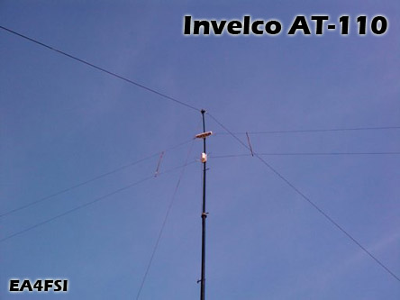
Invelco AT-110 folded dipole antenna
|
Main → HF Radio Resources Center → HF Antennas → Invelco AT-110 → Model validation |
![]() Este artículo también está disponible en Español (this article is also available in Spanish).
Este artículo también está disponible en Español (this article is also available in Spanish).
3. Model validation.
In order to validate the models, I have tried the following inverted-vee configurations of the antenna, simulating masts of different heights (9, 12, 15 and 18 m) and leaving the tips of the antenna at 0,5 m over ground:
-
HM=9, HE=0,5, alpha=72,32º.
-
HM=12, HE=0,5, alpha=65,75º.
-
HM=15, HE=0,5, alpha=58,81º.
-
HM=18, HE=0,5, alpha=51,31º.
For each model described and using those four configurations, I have made the following tests: geometric check, segment check, convergency test and average gain test (AGT), with the results described in this section.
The geometric and segment checks have been done in the limits of the band (2 MHz and 30 MHz).
The convergency and average gain tests have been done in the following discrete frequencies: 2 MHz, 5 MHz, 10 MHz, 15 MHz, 20 MHz, 25 MHz and 30 MHz.
3.1. Model 1.
The results of the validation tests for the first model are described in this section.
3.1.1. Configuration HM=9, HE=0,5, alpha=72,32º.
I have tried the segment densities shown in the table 3:
| Wire | Description | TEST 1 | TEST 2 | TEST 3 |
|---|---|---|---|---|
| 1 | Wire with generator | 3 | 3 | 3 |
| 2 | Left leg | 56 | 112 | 185 |
| 3 | Separator left leg | 6 | 6 | 6 |
| 4 | Left leg | 56 | 112 | 185 |
| 5 | Wire with load | 3 | 5 | 7 |
| 6 | Right leg | 56 | 112 | 185 |
| 7 | Separator right leg | 6 | 6 | 6 |
| 8 | Right leg | 56 | 112 | 185 |
Please note that the load R is always placed in the central segment of the wire (different on each case).
Using the configuration TEST 1, I have achieved AGT values between 1,01 and 1,02 for all the frequencies simulated.
Using the configurations TEST 2 and TEST 3, the AGT results 1,00 (very precise model). After performing the convergence
test, the configuration TEST 3 is finally chosen.
3.1.2. Configuration HM=12, HE=0,5, alpha=65,75º.
I have tried the same segment densities described in the table 3.
Using the configuration TEST 1, I have achieved an AGT value of 1,01 for all the frequencies simulated.
Using the configurations TEST 2 and TEST 3, the AGT results 1,00 (very precise model). After performing the convergence
test, the configuration TEST 3 is finally chosen.
3.1.3. Configuration HM=15, HE=0,5, alpha=58,81º.
I have tried the segment densities shown in the table 4:
| Wire | Description | TEST 1 | TEST 2 | TEST 3 |
|---|---|---|---|---|
| 1 | Wire with generator | 3 | 3 | 3 |
| 2 | Left leg | 56 | 112 | 185 |
| 3 | Separator left leg | 6 | 6 | 6 |
| 4 | Left leg | 56 | 112 | 185 |
| 5 | Wire with load | 3 | 7 | 7 |
| 6 | Right leg | 56 | 112 | 185 |
| 7 | Separator right leg | 6 | 6 | 6 |
| 8 | Right leg | 56 | 112 | 185 |
Using the configuration TEST 1, I have achieved an AGT value of 1,01 for all the frequencies simulated. Using the configurations TEST 2 and TEST 3, the AGT results 1,00 (very precise model). After performing the convergence test, the configuration TEST 3 is finally chosen.
3.1.4. Configuration HM=18, HE=0,5, alpha=51,31º.
I have tried the segment densities shown in the table 5:
| Wire | Description | TEST 1 | TEST 2 | TEST 3 |
|---|---|---|---|---|
| 1 | Wire with generator | 3 | 3 | 3 |
| 2 | Left leg | 56 | 112 | 185 |
| 3 | Separator left leg | 6 | 6 | 6 |
| 4 | Left leg | 56 | 112 | 185 |
| 5 | Wire with load | 3 | 7 | 11 |
| 6 | Right leg | 56 | 112 | 185 |
| 7 | Separator right leg | 6 | 6 | 6 |
| 8 | Right leg | 56 | 112 | 185 |
Using the configuration TEST 1, I have achieved an AGT value of 1,01 for all the frequencies simulated. Using the configurations TEST 2 and TEST 3, the AGT results 1,00 (very precise model). After performing the convergence test, the configuration TEST 3 is finally chosen.
3.2. Model 2.
The results of the validation tests for the second model are described in this section. Due to the fact that in this model all the wires have the same lengths with independence of the configuration used to install the antenna, I have tested the segment densities shown in the table 6, which are valid for all the cases.
| Wire | Description | TEST 1 | TEST 2 | TEST 3 |
|---|---|---|---|---|
| 1 | Wire with generator | 3 | 3 | 3 |
| 2 | Left leg | 56 | 112 | 186 |
| 3 | Separator left leg | 6 | 6 | 6 |
| 4 | Left leg | 56 | 112 | 186 |
| 5 | Wire with load | 3 | 3 | 3 |
| 6 | Right leg | 56 | 112 | 186 |
| 7 | Separator right leg | 6 | 6 | 6 |
| 8 | Right leg | 56 | 112 | 186 |
3.2.1. Configuration HM=9, HE=0,5, alpha=72,32º.
Using the configuration TEST 1, I have achieved AGT values between 1,01 and 1,02 for all the frequencies simulated. Using the configurations TEST 2 and TEST 3, the AGT results 1,00 (very precise model).
The segment validation tests performed with the configurations TEST 1 and TEST 2 show a warning indicating lack of alignment with some parallel segments at 5 MHz.
After performing the convergence test, the configuration TEST 2 is finally chosen.
3.2.2. Configuration HM=12, HE=0,5, alpha=65,75º.
Using the configuration TEST 1, I have achieved AGT values between 1,01 and 1,02 for all the frequencies simulated. Using the configurations TEST 2 and TEST 3, the AGT results 1,00 (very precise model).
The segment validation tests performed with the configurations TEST 1 and TEST 2 show a warning indicating lack of alignment with some parallel segments at 5 MHz.
After performing the convergence test, the configuration TEST 2 is finally chosen.
3.2.3. Configuration HM=15, HE=0,5, alpha=58,81º.
Using the configuration TEST 1, I have achieved an AGT value of 1,01 for all the frequencies simulated. Using the configurations TEST 2 and TEST 3, the AGT results 1,00 (very precise model).
The segment validation tests performed with the configuration TEST 3 show a warning indicating lack of alignment with some parallel segments at 5 MHz.
After performing the convergence test, the configuration TEST 2 is finally chosen.
3.2.4. Configuration HM=18, HE=0,5, alpha=51,31º.
Using the configuration TEST 1, I have achieved an AGT value of 1,01 for all the frequencies simulated. Using the configurations TEST 2 and TEST 3, the AGT results 1,00 (very precise model).
The segment validation tests performed with the configurations TEST 1 and TEST 2 show a warning indicating lack of alignment with some parallel segments at 5 MHz.
After performing the convergence test, the configuration TEST 2 is finally chosen.


|
Ismael Pellejero - EA4FSI |
 EA4FSI Home |
 HF Antennas |
 HF Central |