 EA4FSI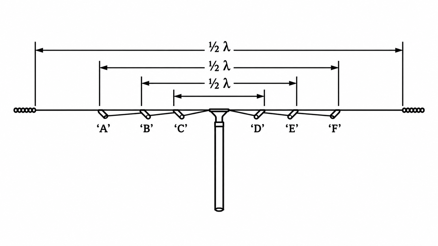
Warning: This model is provisional and is still being revised. The results may be inaccurate or contain errors.
| Type | Multiple dipole |
|---|---|
| Design | REMER |
| Impedance | Variable |
| Simulation | MMANA-GAL |
| Band | Multiband |

1. Antenna design and modelling.

The antenna consists of several half-wave dipoles, each cut to a length corresponding to one of the operating bands. The operating bands in this design are 10, 20, 40 and 80 m. The arms of the dipoles on each side are connected together at a common feed point.
2. Simulation results.
This section presents the MMANA-GAL simulation results, including the calculated standing-wave ratios (SWR) and radiation patterns for each band.
2.1 Standing wave ratios (SWR).
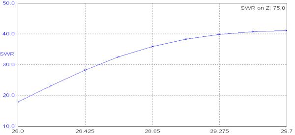
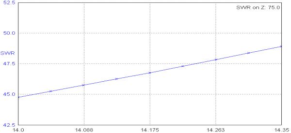
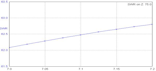
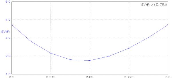
The SWR values are calculated for a transmission-line characteristic impedance of 75 Ω. Achieving resonance on every band may be difficult, so it is recommended to use an antenna tuner. A suitable transmission line is 75 Ω twin-lead cable, although 50 Ω or 75 Ω coaxial cable may also be used.
Figures 2–5 show, respectively, the standing wave ratios calculated for the 10 m, 20 m, 40 m and 80 m bands.
2.2 Radiation patterns.
- 10 m band: the radiation pattern is mainly bidirectional, with two main lobes along the antenna axis and several secondary perpendicular lobes. The simulated gain is approximately 7 dBi (Fig. 6).
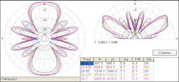
- 20 m band: the radiation pattern is bidirectional, with its main lobes along the antenna axis and a simulated gain of approximately 3 dBi. The main lobes have an elevation angle of approximately 50° (Fig. 7).

- 40 m band: the radiation pattern is weakly bidirectional, with its main lobes perpendicular to the antenna axis. The simulated gain is approximately 5.2 dBi. The radiation pattern is suitable for NVIS propagation (Fig. 8).
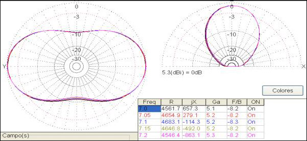
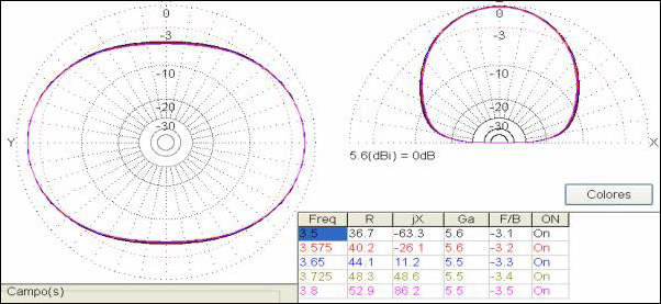
- 80 m band: the radiation pattern is approximately omnidirectional, with a simulated gain exceeding 5.5 dBi. The radiation pattern is suitable for NVIS propagation (Fig. 9).